Building a Cryptocurrency Mining Rig - Part 1
When Ethereum exploded in popularity (and value) in Summer of 2017, I decided to educate myself about cryptocurrencies and blockchain technology. As part of that process, I built an Ethereum (Classic) mining rig.
Here I’ll discuss how I designed and built my miner, focusing primarily on the construction of the chassis using OpenBeam, Fusion 360, and a Shapeoko 3. (Later, I’ll discuss BIOS configuration in Part 2, mining strategy optimization in Part 3, and compute performance optimization in Part 4.)
If you’re not interested in the design/build process, click here to skip to the end result.
Component Research
My strategy for the build was first to choose the mining hardware (the “guts” of the machine), and then design the chassis around it. Having never built a miner before, I began by researching what hardware was typically used for mining.Google quickly turned up Cryptobadger’s blog, which I found to be enormously instructive. I learned the following from his series on building a mining rig:
The power-supply should have headroom beyond GPU consumption.
Few motherboards have sufficient (6+) PCI-E sockets for attaching GPUs.
Few GPUs are optimal for mining in terms of hashes per watt.
GPUs aside, powerful hardware is of little importance.
GPUs
I researched the common mining GPUs, and chose the EVGA GeForce GTX 1070 for a few reasons:They are energy-efficient, and thus inexpensive to power over the long-term.
As low-power GPUs, I assumed they would run cooler than other options. (This is important to me because I live in Florida, and didn’t want my miner to be a space-heater.)
These GPUs will be used in Linux workstations when retired from mining, and I prefer NVIDIA to AMD for that use-case.
Other Components
I also purchased two 3.5-inch hard-drives: an SSD for the operating system and applications, and an SHDD for blockchains. (I intend to run full Bitcoin and Litecoin nodes, and perhaps others.)The remaining hardware decisions were relatively unimportant. If you’re interested in those details, see the bill of materials at the end of this article.
Chassis Design
With the hardware decisions made, I began designing the chassis.Research
Once again I started the process by researching what others had done. The following approach appeared to be relatively common:Build a lay-flat rectangular frame
Zip-tie GPUs side-by-side inside the frame
Mount the motherboard and power supply beneath the GPUs
Here’s an example from Motherboard:
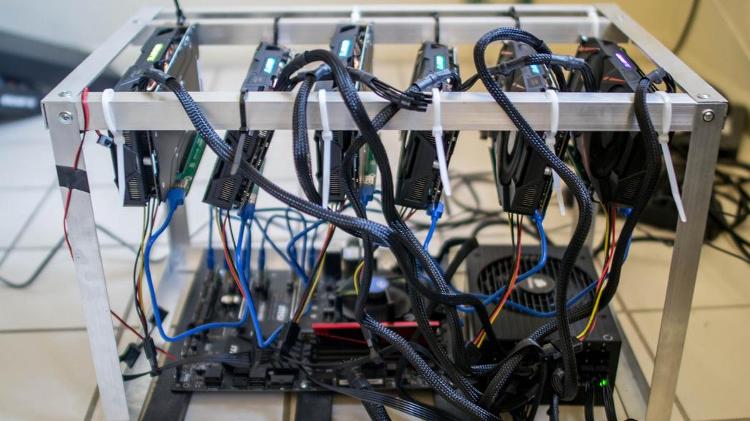
The lay-flat solution seemed practical and inexpensive, but I had a few issues with it:
Spatial constraints in my apartment forced me to store my miner on my desk, and I was unwilling to sacrifice the amount of desk-space that the lay-flat design would require.
The lay-flat design places all GPUs side-by-side, such that only the outermost GPU has access to cold air - the others' intake fans draw directly from their neighbor’s heat-sink. I feared that this arrangement could contribute to overheating.
Subjectively, I thought many of the lay-flat builds were ugly.
Given the above, I decided to eschew convention and design a vertical miner that resembled a common PC tower.
Development
With a strategy in mind, I began to think through the design details. I eventually decided that:The power supply should be mounted at the bottom of the chassis to provide a low center-of-gravity and minimize the risk of tipping.
Six total GPUs should be positioned above the power supply, in pairs, in three 150mm bays. This arrangement would give 3 of 6 GPUs access to cold air, and would sandwich no GPUs.
The motherboard should be mounted off the side of the chassis, on the side opposite the GPU intake fans (such as not to obstruct cold air intake).
Satisfied with the plan, I began to research construction materials, hoping to find an attractive material that facilitated rapid prototyping. I eventually discovered OpenBeam, which touted itself as “a low-cost, open-source extruded aluminum construction system”:
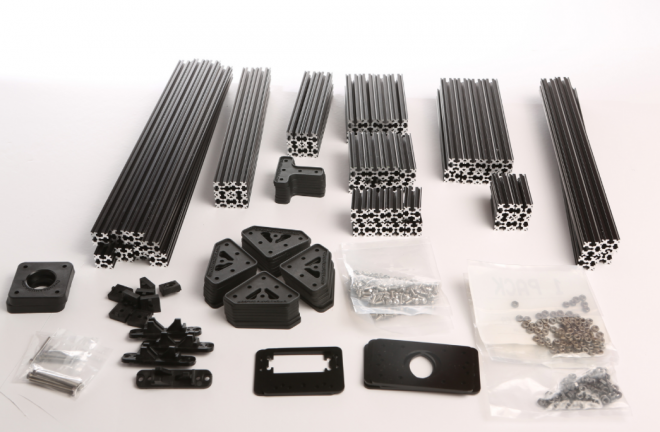
It fit the bill perfectly.
Building the Chassis
Prototyping
I ordered an OpenBeam set, the “mundane” computer components (motherboard, CPU, RAM, etc.), and a single GPU, and then began prototyping the chassis design.OpenBeam was ideal for this application. While I have some experience with Sketchup and Fusion 360, I personally find it easier to reason through spatial problems in “meatspace” when possible. OpenBeam spared me from having to model GPUs and other components in CAD, and enabled me to iterate using real, physical components.
After a few days' worth of experimentation, I settled upon the following design:
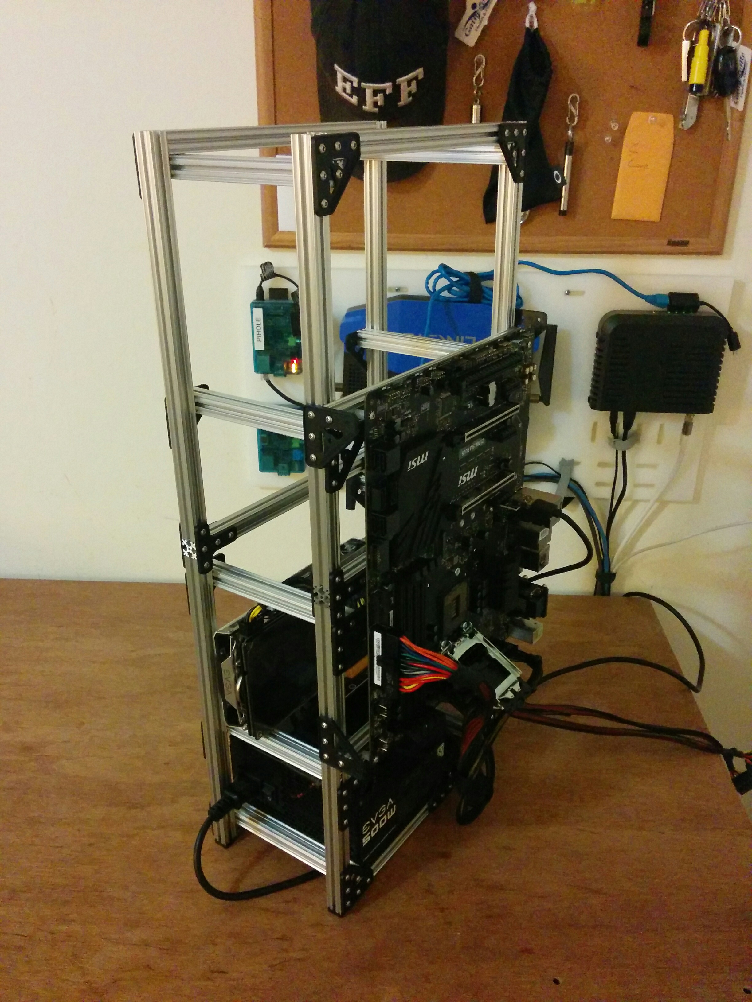

(You’ll see a 500W power supply in the photo. I was using it as a placeholder while I waited for a 1200W unit to arrive in the mail.)
Testing (Round 1)
With the prototype assembled, I decided to sanity-check the miner’s hashrate before purchasing the remaining GPUs. I installed Ubuntu 17.04 Server Edition and configured Claymore to dual-mine ETC and DCR, and ran the miner overnight. The hashrates were consistent with what I expected, so I continued onward.GPU Installation
With the hardware proven, I purchased and installed the remaining five GPUs: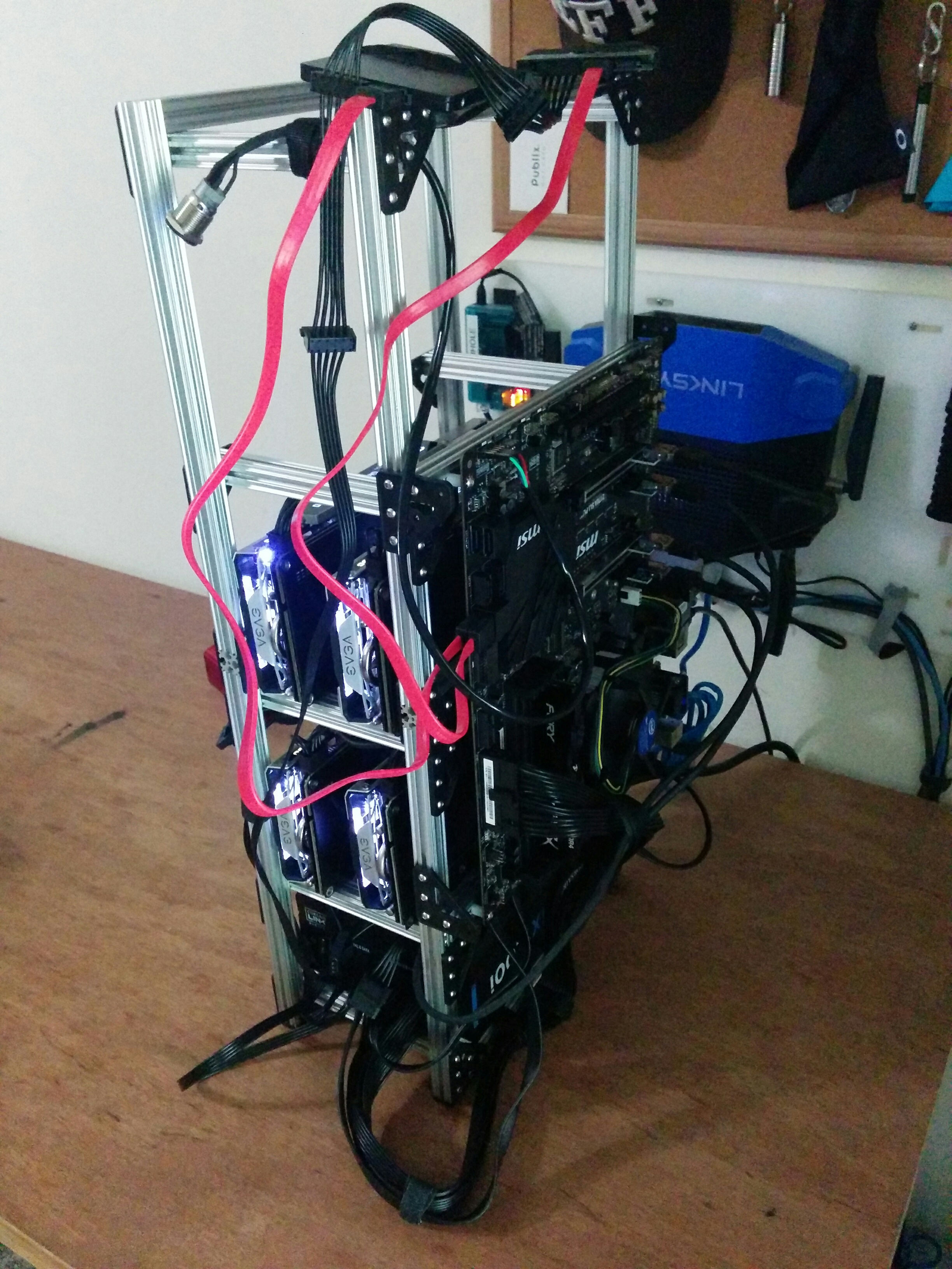
(These pictures were taken before the final two GPUs arrived in the mail.)
Initially, nvidia-smi could not detect two of the new GPUs, and I suspected
that the PCI-E risers were defective. After experimentation, however, I
determined that the risers themselves were fine, but that the USB cables they
shipped with were faulty.
I resolved the problem by replacing all of the PCI-E riser cables with new ones from Amazon, having lost confidence in the factory cables.
I also had to update my motherboard’s BIOS in order to detect more than four GPUs. I’ll discuss that process in detail in Part 2.
Testing (Round 2)
After installing the GPUs, I ran the miner for a few days as a test, and once again achieved the (now higher) hashrates I expected. I only encountered two minor problems:Cable tension would sometimes pull the GPUs together. (You can see this happening in the photos above.)
Some GPUs were getting hot (~80C).
The first problem was easily solved. I purchased aluminum screws and stand-offs from McMaster Carr and constructed locking-lugs to hold the GPUs in place:

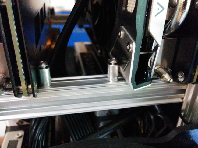
(This would have looked nicer had I purchased shorter screws or taller stand-offs. Oh well.)
The overheating problem required more thought. The obvious solution was to install fans on the chassis, but I was unsure how best to mount them.
As a short-term kludge, I zip-tied a 140mm fan in front of each GPU bay. This cooled the GPUs sufficiently for me to begin mining full-time, and freed me to solve the remaining problems at my leisure.
Side note: I was surprised by how much more effective it was to “suck” hot air away from the GPUs than to “blow” cold air over them (~7C). I oriented the fans to “suck” air accordingly.
Mounting the Power Switch and Hard-Drives
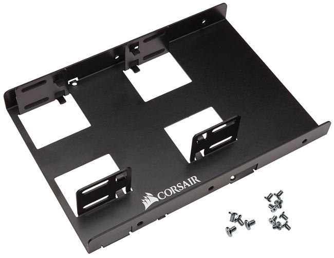
While I mulled over how to permanently mount the fans, I decided to first solve an easier problem: mounting the power switch and hard-drives.Wanting to make the job easier, I started by purchasing a double mounting bracket for the hard-drives:
I then designed a panel for the top of the chassis, and cut it from 1/4" Lexan:
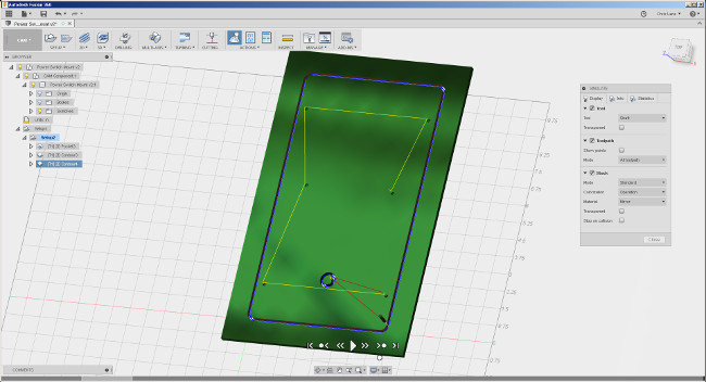
I attached the power switch and hard-drive mounting bracket to the panel, and then attached the panel to the chassis. It held everything neatly in place:
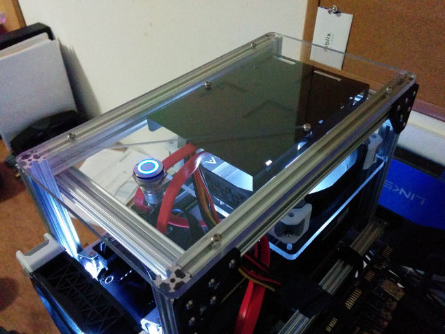
The mar in the photo occurred because my mill failed to withdraw to its “retract height” when travelling to make its first cut. I’m not sure why it did that, but I suspect that I overlooked some parameter in Fusion 360 that I should have set. (I’m really enjoying Fusion 360 so far, but I’ve found that it has a steep learning-curve.)
Milling blemish aside, I thought the panel turned out really well.
Mounting the Fans
With the drives mounted, I turned my attention back to the fans.I wanted to position a fan in front of each GPU bay. Each bay was 150mm wide, and each fan was 140mm wide (with mounting holes slightly closer together than that).
Because I was happy with the Lexan mounting panel for the hard-drives and power switch, my first instinct was to take a similar approach with the fans. I designed and cut a prototype mounting panel:
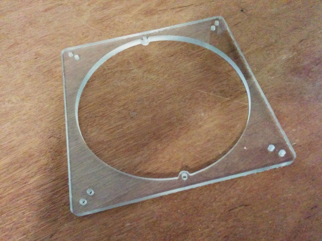
The panel milled perfectly. After experimenting with positioning it, though, I observed some problems:
The holes that mounted the fan to the panel and the holes that mounted the panel to the chassis were so close together (out of necessity) that their screws competed for space.
Each GPU bay had somewhat different geometry due to the hardware used to mount the motherboard to the side of the chassis. Accommodating this would require me to either mill a distinct panel for each bay, or to “jump” some of the mounting hardware with stand-offs.
After staring at the chassis for a bit, I decided to ditch the Lexan panel and opt for a simpler solution - mount the fans directly to a chassis rail:
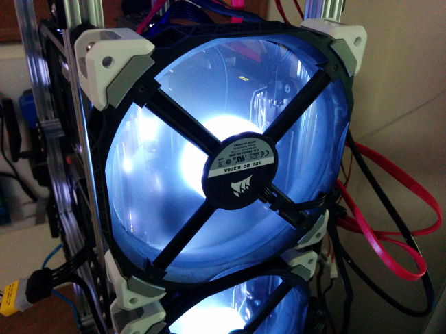
(The fans are white, though they look somewhat blue in the photos.)
(The blue device sitting on top of the chassis is a fan controller. It hadn’t been mounted at this point.)
This approach positioned the fans slightly (5mm) off-center, which is why I avoided it initially. Functionally, though, that was inconsequential, and I found that the aesthetics didn’t bother me. So, I declared that solution “good enough” and moved on.
Mounting the Fan Controller
The final piece of hardware to mount was the fan controller: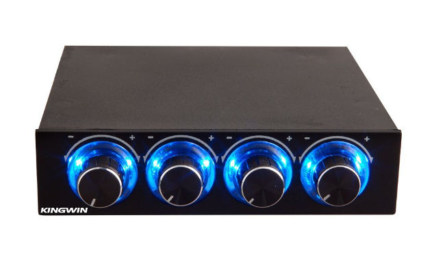
I had initially hoped to mount it above the topmost GPU fan, but the enclosure was too deep, and collided with the power switch.
I then changed plans and decided to mount it off the side of the chassis, above the motherboard. There existed no convenient way to mount the fan controller enclosure to the chassis, though, so I disassembled the fan controller to see if I could drill two holes in its enclosure to use as mount points:
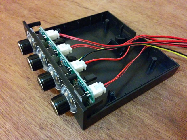
The enclosure turned out to be mostly empty. The useful part of the fan controller was a circuit board attached to the front panel, which lifted effortlessly out of the enclosure:
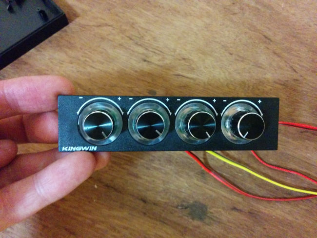
Having discovered this, I discarded the enclosure and returned to my original plan of mounting the fan controller above the topmost GPU fan. I only had to make one modification to the chassis: the fan controller collided with a horizontal strut that connected the tops of the front chassis rails.
The offending strut was structurally unimportant, so I simply removed it. (Thanks to OpenBeam, it only took a few seconds to make this change.)
Next, I once again used Fusion 360 and my Shapeoko to design and cut a Lexan mounting panel for the fan controller:

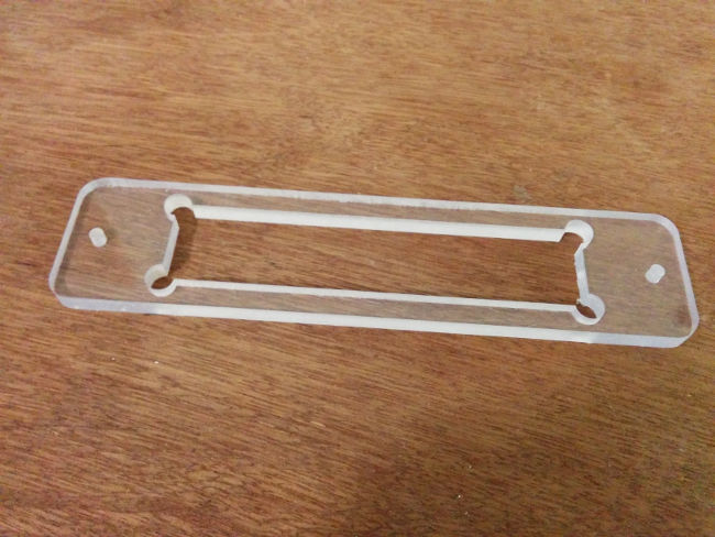
The fan controller snapped cleanly into the mounting panel, and I reinforced its fit with Superglue. (In hindsight, I should have been tidier with the glue.) I then mounted the panel to the chassis:

With the fan controller installed, I powered on the machine and tested the fan acoustics. Dependent on the fan controller settings, the fan noise ranged from “barely audible” to “oscillating desk fan”. Even at the highest setting, the fan noise never became unpleasant.
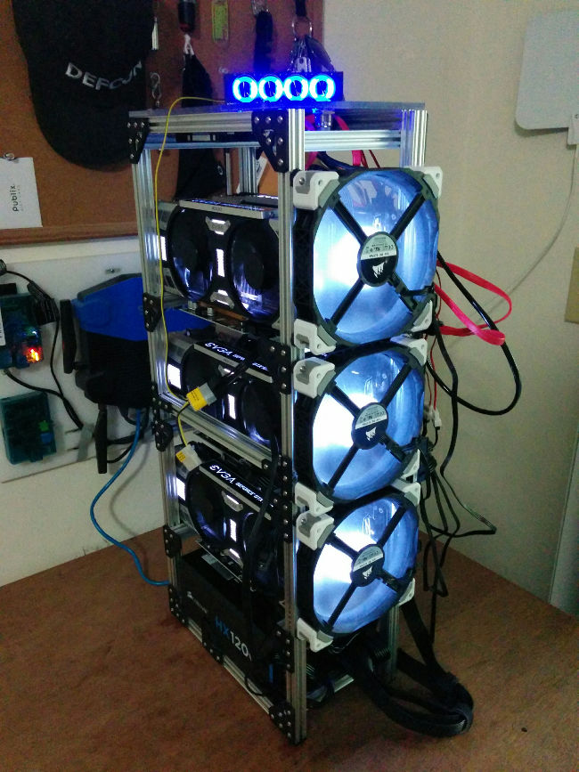
The End Result
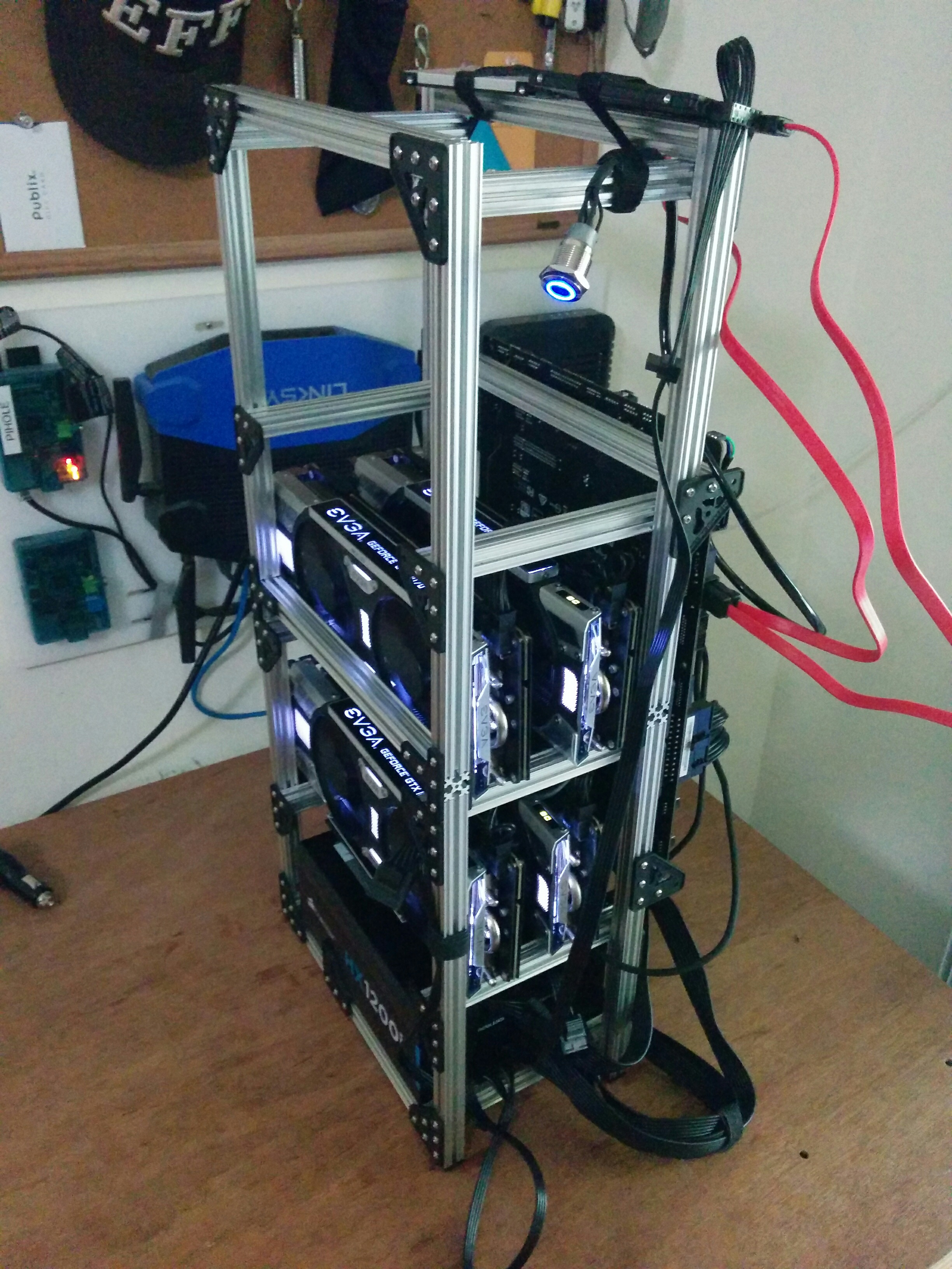
Completed photos, daytime and nighttime: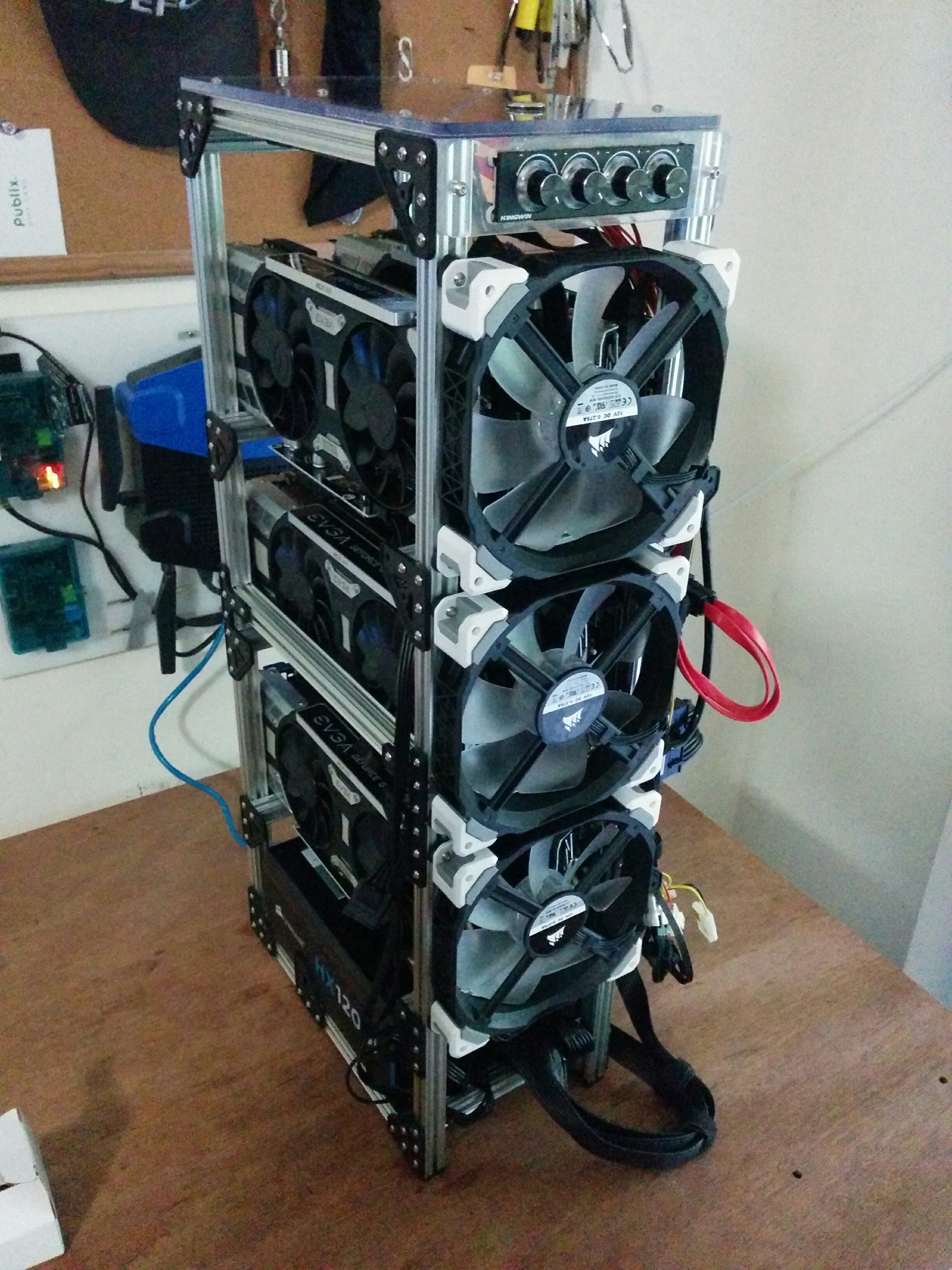

With that, physical construction of the chassis was complete. In Part 2, I’ll discuss the BIOS changes that were necessary to bring all six GPUs online and fix corrupted video output.
If you have any questions or comments, tweet to me at @chrisallenlane.
Appendix: Bill of Materials
I used the following items for the build. (Disclosure: these are affiliate links.)- OpenBeam Precut Construction Kit (x1)
- OpenBeam 1515 x 150mm, 8 Pack (x1)
- Corsair HX1200i 1200 watt power supply (x1)
- 16 mm chassis switch (x1)
- MSI Pro Solution Intel Z710A ATX motherboard (x1)
- Intel Celeron G3900 2.8GHz processor (x1)
- Kingston 4GB RAM (x1)
- EVGA GeForce GTX 1070 SC (x6)
- PCI-E powered riser (x1 pack of 6)
- USB 3.0 cable (x6)
- Seagate FireCuda 2TB SSHD (x1)
- Samsung 120GB SSD (x1)
- Corsair Dual SSD mounting bracket (x1)
- Male to female SATA power splitter (x1)
- Corsair 140mm fan (x3)
- Fan controller (x1)
- Lexan Sheet (x2)
- Velcro One Wrap Thin Ties (x1 roll)
- Kill-A-Watt (x1)
Appendix: node-nvidia-smi
While experimenting with implementing node wrappers around various mining processes, I developed and published node-nvidia-smi, which exposes information fromnvidia-smi to a node environment.